Tue Jan 30 18:58:24 EST 2001
James Fung (fungja@eyetap.org) and Steve Mann (mann@eecg.toronto.edu)
Many PICs are supported in GNU Linux, but unfortunately we needed to use a PIC that had enough input pins, and have not been able to find nonviral support for it. If anyone finds nonviral support for it, please let us know.
Go to the Bluetooth lab, in Sandford Fleming Building Room SF2202, and use the Virus2000, and run the 'MPLAB' software.
Go to 'file' and 'Create a New Project'. This opens up a dialogue box. Near the bottom, click on the .hex file, and click the bottom right button which opens up another dialogue box. Click ok. Then, click on the .hex file again, and, to the right, click on 'Add file' or whatever. Find the .asm file you're using.
Then find the 'Build All' option from the top drop down menus, and click it.
Then, find the 'Start Programmer' (or something similar) click it. Insert the PIC. The PIC has a gold mark on the top near pin 1. Place the PIC in the programmer so PIC pin 1 is in the corresponding pin 1 slot on the programmer.
There's a set of 5 options: Clock, Watchdog, Code Protect and so on. Look in your .asm file and see what it says about setting these. For instance a line like:
#include "P16C63.INC" __config _HS_OSC | _WDT_ON | _PWRTE_OFF | _CP_OFF | _BODEN_OFFmeans you should set the Clock to "HS", Turn on Watchdo timer, and turn off everything else.
Click 'blank' to see if the device is erased.
Click 'Program' to program it with whatever is in the hex mapping window. (which'll be the hex code of the .asm program we just compiled).
Click 'verify' to make sure it worked ok.
And now you have a programmed PIC. Put it in an existing one-handed keyboard to verify everything is OK with the PIC.
Finally, to erase the PIC, place it in the UV erase, with the window facing down and turn on the eraser.
Get a blank circuit board.
Wire in the IC socket, resistors, capacitors, crystal, LED socket (RJ11), and keyer socket (RJ45). Until we get a picture up here, take a look at someone else's board to see how to place the components.
You have a choice to either connect a PS/2 cord directly to the board, or to solder a socket to the board. We prefer to solder the wires directly to the board. In this case, take a standard PS/2 cable (cord with male connector at both ends) and cut it in half. This can be used for 2 keyers (one half for each keyer). Connect the PS/2 cable by cutting the cable and connecting the wires directly to the board. Check the continuity to preserve the way that a PS/2 connector should be connected. NOTE THAT COLORS IN THE PS/2 CABLES ARE OFTEN ARBITRARY AND INCONSISTENT, E.G. THE RED WIRE IS OFTEN GROUND, OR THE BLACK WIRE MAY BE +5VOLTS, ETC.; IN GENERAL CHECK THE CONTINUITY AND DON'T TRUST OR GO BY THE COLORS OF THE PS/2 CABLE WIRES. For the PS/2 pinout, you can consult the Hardware Book. A search on "hwb" and "hardware book" on altervista (http://eyetap.org/s) should do the trick.
A strain relief for the PS/2 cable is a good idea.
Leave a good amount of cable when you wire cables up. This will help keep strain away from the board and the solder connections.
Connect the RJ45 cable to the board as follows:
solder female for pcb mount, pins facing you, and the pins correspond to common, key7, key6, key5, key4, key3, key2, key1, as follows:
 c k k k k k k k
 o e e e e e e e
 m y y y y y y y
 m 7 6 5 4 3 2 1
 o
 n

+----------------+
|o   o   o   o   |
|                |
|  o   o   o   o |
|                |
|                |
|                |
|                |
|                |
|                |
|                |
+----------------+
For compatibility with previous keyers (e.g. if you meet one of us at a confernece or in class and want to swap keyers), you should adhere to this pinout convention, and so mount the keyer socket backwards on the bottom of the board. Ask one of us in class how to mount the RJ44 socket.
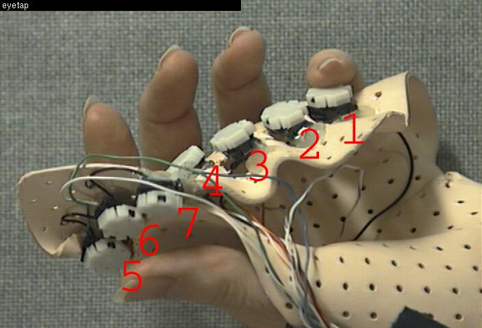
The switch numbers correspond to the left hand buttons, as shown
in the following figure:
(for the benefit of the visually challenged, the above jpeg contents are roughly as follows)
finger          key switch number
------          --------
Pinkey finger = key1
Ring finger   = key2
Middle finger = key3
Index finger  = key4
Thumb switches = 5,6,7, with key5 being closest as the bug crawls
along the keyer from key4 (index finger key) to that switch.
Get a working handset, your working PIC, and test your board out.
Take a look at the septambic howto link from http://wearcam.org/septambic for more info.